Import 3D Model into Single or Two Sided Job
 Initial Orientation
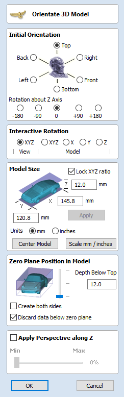
Choose one of the 6 options to determine the most suitable direction on the model that defines the top surface (upper Z) that you want to use when it's converted into a Component.
You can also use the five options for Rotation about Z Axis to modify the position of the part being imported at this stage.
Interactive Rotation
The default choice XYZ-View allows you to left-click in the 3D View with the mouse to rotate your view so you can examine the part from different angles. Using this will not change the orientation of the part for import. If you select one of the other four options above the word Model then this will adjust the actual positional orientation of the imported part. Choosing the XYZ option will allow rotation around all three axes simultaneously, X, Y or Z will only allow rotation around the specified axis. This is also done using the left-click in the 3D View with the mouse.
Model Size
Lock XYZ ratio
Un-checking this option allows the model to be distorted from its original shape. This means independent X, Y and Z sizes can be entered. Leaving it checked ✓ fixes the ratio so it cannot be distorted. Instead it will automatically scale the other axes as you enter new values for X, Y or Z.
Apply
Applies the values you have entered for the X, Y or Z dimensions.
Many mesh files do not inherently have the units that they were made in embedde in the files, so the software is not able to tell if the files are supposed to be inches or metric, they will just have a particular value. Therefore it is quite common to need to scale the part from inch to metric or vice versa. If you import your model and you wish to work in inches and the file seems very large or if you work in Metric and the file seems very small then you will probably need to use the Scale mm/inches option. The next two items on the form cover this need.
Units
Choose the unit of measurement (mm or inches) that you are working in, within the part the file is being imported into.
Changing the units will result in resizing the model. For example, if you had 5x5 mm dimensions, they would become 5x5 inches so the model becomes a lot larger.
Scale mm/inches
Scales the X, Y and Z values up or down depending which Unit option is selected. If mm is selected then the software assumes you want to scale the values up so multiplies the current values by 25.4, if inches is selected it assumes you want to scale the values down and divided them by 25.4.
Zero Plane Position In Model
This slider bar determines where the 3D model will be cut-off when converting to a Component. You can move this up and down with the mouse or use the Middle or Bottom buttons to locate the plane in the correct position.
Note
Anything in the original model which is an undercut (goes underneath another part of the 3D model) will be discarded and a vertical wall will be created down to the plane from the silhouette (looking down Z axis) edge of the model.
Discard data below zero plane
Checking ✓ this will remove any data below the original Zero level within the imported 3D model. If the model is effectively a negative model such as a dished or recessed design with a flat plane then you should uncheck this option to make sure you retain the 3D data below the plane.
Create both sides
If you are working in a 2 sided setup you can check ✓ this option and two components will be created - one looking down the Z axis from above to the zero plane and one looking up from below. Each side of the model will go onto a side. This will provide you with the geometry that can be edited to cut the original imported 3D part as a 2-sided job.
If you were importing a model that contains a non-convex surface for instance a bowl you can import the entire model on each side by sliding the slicing plane all the way to the bottom.
Center Model
The button which will move the center of the model's bounding box to datum position (XYZ zero). This is particularly useful if you intend to unwrap a model for rotary machining. This may change the Zero Plane position in the model.
Apply Perspective along Z
Checking ✓ this will enable you to apply a perspective distortion to the model along the Z axis by using the slider. Points on the model closest to the observer will become further apart as the distortion strength is increased - this makes the model appear as if it is coming out of the screen.
OK
Creates a 3D Component based on the settings in the form, the Component will have the same name as the imported file. If you selected 'Create both sides' you will have two components with the name of the imported file followed by the suffixes -Top and Bottom.
Cancel
Cancels the Import function and returns to the standard Modeling Tab icons.